Checkout using your account
Checkout as a new customer
Creating an account has many benefits:
- See order and shipping status
- Track order history
- Check out faster
How do replace a digital pumped processor with a standard (unpumped) processor
A2 and A1 Smart Valves share the same hot and cold inlet centres however, the location of the mixed supply pipe differs and would need altering if changing from gravity to high pressure. In many cases, this will be an extra elbow connection - below are images both Smart Valves and the location of the mixed supply pipe.
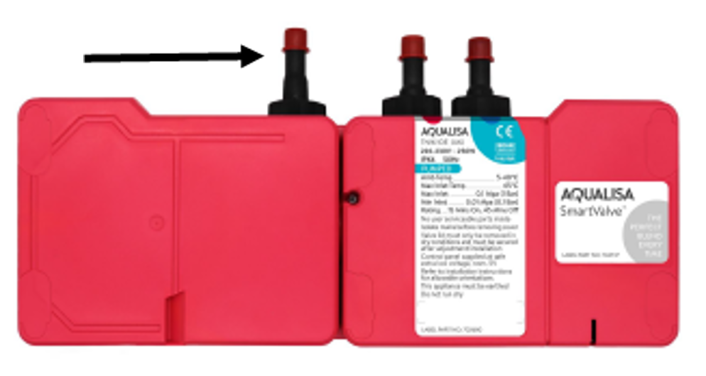
A2 Gravity Pumped Smart Valve
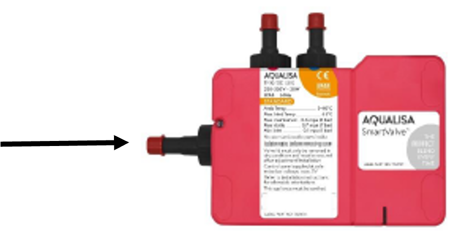
A1 Gravity Pumped Smart Valve
1. You would first need to Unscrew the 4 feet each corner of the Smart Valve.
2. Isolate the main circuit on which the Smart Valve is connected
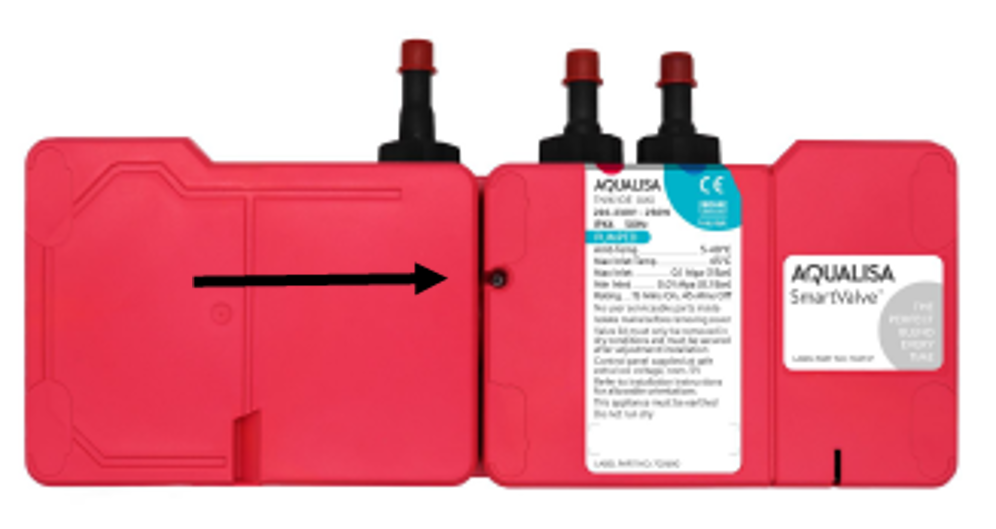
3. Remove the data cable from the Smart Valve. To do this, the lid must be removed by loosening the single screw between the 2 lids of the Smart Valve (image below). The data cable can be removed by pushing on the lever that secures the cable plug into the Logic Module.
4. Water must also be isolated. Smart products are supplied with isolation valves which should have been used in the installation. Using a flat head screwdriver, turn the groove 90 degrees so that it is positioned across the valve rather than parallel with the pipe. Repeat for the remaining 2 isolation valves. If the isolation valves are also required to be replaced, further isolation of the water system will be required on the hot and cold tanks to avoid draining down the system. If the system must be drained, this could potentially cause airlocks when refilled.
5. Remove the Smart Valve from the pipes. To do this, push on the release collars (black rings) on the isolation valves to disengage the grippers from the black processor spigots.